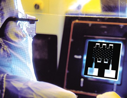
 DIE
DIE
A die is a single complete device image. A primary die (also called the primary pattern) contains the device design that is used to make the circuit. Most of the array is made up of primary dice. A test die contains a simplified functional device (of the same process type as the primary die). The test die is used for process control and monitoring during wafer fabrication and sometimes to test new design ideas.

1X Master primary and test dice.
SCRIBE LINES (SCRIBES)
Scribe lines (scribes) are the lines forming a border around each die separating the dice from one another and used as a guide for separating the individual die by sawing. Small patterns can be placed within these scribes, usually for alignment marks or test patterns used in wafer fabrication.

Scribe lines.
ARRAY
The array is the area made up of the rows and columns of dice on 1X masters, 5X reticles and other reduction reticles.
1X MASTERS
The 1X Master mask has many repetitions of the primary pattern (the principle circuit design). Each complete pattern is also called a die. Unlike reticles, which are stepped, the patterns on the 1X Master photomask are projected onto the substrate only once – all the repetitions of the device are on the mask itself.

Example of 1X Master array.
WAFER-STEPPER RETICLES
The patterns on a wafer-stepper reticle are stepped (projected) onto the substrate many times placing the patterns next to one another. The patterns on the reticle are sometimes scaled at 1X, but oftentimes the reticles are scaled larger at 2X, 4X, 5X or 10X. The scaled reticles are optically reduced as they are stepped so that the pattern transferred to the wafer ends up at 1X. This means the dice on the photomask may be 4, 5 or 10 times larger than they are on the final product. The scale of the reticle is determined by the wafer stepper in which it is to be used. Wafer-stepper reticles are used on a variety of steppers.

Example of 5X Reticle mask.
FIELD
Field is the unused part of the plate that surrounds different patterns. A field can be dark or clear. A dark field means that the outside of the pattern area is covered with the coating materials (opaque) while a clear field refers to the pattern area where the coating is kept.
Field refers to the tone of certain regions of the photomask. Field may be expressed in terms such as “light field” or dark field” or “clear field” or “opaque field”. As previously mentioned, these polarity designations are open to interpretation and not specific enough to be reliable. Dark and clear regions of the photomask should be very specifically indicated whenever possible. This can be achieved by marking regions of a paper plot of the device as “dark or clear”. An alternate method would be to indicate that the “drawn or digitized” areas of the customer-supplied data are to be either “dark or clear”.
ROW
A row consists of a horizontal line of dice on the photomask.
COLUMN
A column consists of a vertical line of dice on the photomask.
FIDUCIALS
Fiducials are patterns on reticles used for alignment on wafer steppers. Each brand and model of wafer stepper requires specific types of fiducial patterns. The fiducials are usually located outside of the array.

Mask Fiducials.
REFERENCE MARKS FOR AUTO-INSPECTION
Reference marks are internal marks placed in the corners of the mask. These marks are used as points of reference when setting up inspection on an automated inspection system (such as a KLA system) and when repairing defects found by such inspection.

Reference mark.
PHOTOMASK INSPECTION
In order for the circuits being made from the photomask imagery to function, the photomask must meet customer specifications. The masks are inspected for critical dimensions, defects, registration, and contamination before being sent to the customer.
CRITICAL DIMENSIONS
Certain geometries on the mask with specific sizes are used as a gauge. These geometries are called critical dimensions or CDs. The designer indicates the target size or spec of the CDs in microns or mils and the acceptable variance from that target (the tolerance).
CD (CRITICAL DIMENSION) MEASURING
CDs are measured on a microscope to make sure the CD size is within the customer specification.

Typical Example of geometry used as CD 1.5.2.
REGISTRATION
Registration (absolute) – Indicates the relationship of the placement of the mask features as compared to NIST certified standard grid. Absolute registration must be verified using a calibrated X & Y measuring system.
Registration (layer to layer) – Indicates the relationship as a comparison of one photomask in a mask set to any other photomask in that same mask set. Layer to layer registration may be verified using either a calibrated X & Y measuring system, or by using an optical comparison system which allows the inspector to simultaneously view 2 mask layers with overlay simulated by optics.
DIE REGISTRATION
Registration or alignment of dice on a mask in relation to other layers in the device or to a design grid.
ARRAY REGISTRATION
Registration or alignment of the whole array on a mask in relation to other layers in mask set.

Examples of Registration.

